Reset chip works on 24V rails and wastes only 300nA
Author: EIS Release Date: Aug 29, 2019
Texas Instruments has introduced a reset chip for voltage rails between 1.5V and 10V, that can work on 24V rails with additional resistors (see below).
Called the TPS3840 family, supply current is typically 300nA, and is 700nA max over temperature.
Threshold voltage is fixed, and versions are available from 1.6 to 4.9V in 0.1V steps – accuracy is 1% typ (1.5% max). Hysteresis is typically 100mV for 1.6 to 3.0V versions, and 200mV for 3.1 to 4.9V.
“The devices provide a combination of minimal power consumption, high accuracy, and low propagation delay to help extend battery life for a variety of low-power, industrial, and battery-powered applications,” according to Mouser, which is stocking the parts. “With less than a 1µA current consumption, the ICs can be configured to work as either a comparator – with a simple three-pin configuration – or as a daisy-chained universal power supply supervisor that acts as a sequencer.”
Minimum supply voltage for a meaningful output (‘power-on-reset’, according to TI) is 300mV and, with rising power, the device is ready to operate 220µs (typ) after crossing this (350µs max).
“The devices’ fast start-up delay allows the detection of a voltage fault before the rest of the system powers up, providing maximum safety in hazardous start-up fault conditions, and the low power-on-reset prevents false resets, premature enable or turn-on of next device, and proper transistor control during power-up and power-down,” said Mouser.
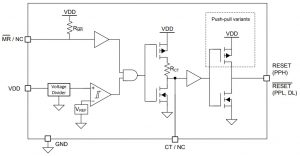
The connection CT/NC allows a capacitor to be connected to delay the reset pulses – values span 50µs with no capacitor to 6.2s with 10µF.
There is also an active-low manual reset, and there are three output options:
- open-drain, active-low (TPS3840DL)
- push-pull, active-low (…PL)
- push-pull, active-high (…PH)
Operation is across -40 to +125°C, and the devices come in a five-pin SOT-23 package.
Higher voltage working
To keep the device below its 12V absolute maximum Vdd, TI recommends using a two resistor potential from the rail to be sensed to the Vdd pin of the chip – suggesting, for example, a 10.5kΩ top resitor and 10kΩ bottom resistor for a 4.9V device connected to a 12V rail (Fig 51 and equation 7 in the data sheet). The reset output remains low-voltage-only (Vdd + 300mV abs max).
“Notice that the resistor values chosen are less than 100kΩ to preserve the accuracy set by the internal resistor divider,” according to the data sheet. “Good design practice recommends using a 0.1-µF capacitor on the VDD pin and this capacitance may need to increase when using an external resistor divider.”
Applications are foreseen in grid infrastructure (circuit breakers, smart meters), factory automation, building automation, electronic point-of-sale, portable equipment, battery-powered systems, according ot Mouser.